Chapter: Installation
Product Features Connecting the Equipment Configuration and Management of the ATA Mounting the ATA
Product Features
Top Panel
| | |
|---|---|
 | |
 | |
 | |
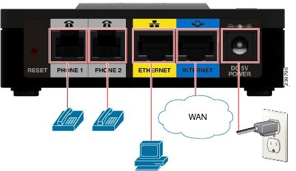
Back Panel
| | |
|---|---|
| Reset | |
| Phone 1, Phone 2 (Gray) | |
| Ethernet (Yellow) SPA122 Only | |
| Internet (Blue) | |
| Power | |
Connecting the Equipment
NOTE For wall-mounting instructions, see Mounting the ATA.
STEP 1![]() Connect one end of the provided Ethernet cable to the Internet (Blue) port. Connect the other end directly to your broadband network device.
Connect one end of the provided Ethernet cable to the Internet (Blue) port. Connect the other end directly to your broadband network device.
STEP 2 Connect one end of a phone cable to the Phone 1 (Gray) port. Connect the other end to your analog phone or fax machine.
STEP 3 Connect one end of another phone cable to another analog phone or fax machine. Connect the other end to the Phone 2 (Gray) port.
STEP 4 SPA122 Only: Optionally, connect one end of an Ethernet network cable to the ETHERNET (Yellow) port of the ATA. Connect the other end to a device on your network, such as a computer.
STEP 5 Connect the provided power adapter to the Power port.
Configuration and Management of the ATA
You can use the web-based configuration utility to set up your ATA. You also can use the built-in Interactive Voice Response (IVR) system.
Using the Web-Based Configuration Utility
STEP 1![]() Connect your computer to the same subnet as the ATA. For example, if the ATA is connected to a LAN port on your router, also connect your computer to a LAN port on your router.
Connect your computer to the same subnet as the ATA. For example, if the ATA is connected to a LAN port on your router, also connect your computer to a LAN port on your router.
Note: On SPA122, you can connect your computer to the ETHERNET (Yellow) port of the ATA.
STEP 2 Power on your computer.
NOTE: Make sure your computer’s Ethernet adapter is set to obtain an IP address automatically. For more information, refer to the Help for your operating system.
STEP 3 Start a web browser on your computer.
STEP 4 In the Address bar, enter the IP address of the ATA.
- SPA112: Use the ATA’s IVR or your router’s configuration utility to find the dynamically assigned IP address of the ATA. For information about the IVR, see Using the IVR for Administration.
- SPA122: In the Address bar, enter: 192.168.15.1
Note: 192.168.15.1 is the default local IP address of the ATA.
STEP 5 To log in for the first time, enter the default username, admin, and the default password, admin. The password is case sensitive.
STEP 6 Enter the Connection Type and settings required by your Internet Service Provider. Types include DHCP (the default option), Static IP, and PPPoE (required for most DSL service). After entering these settings, click Submit to establish your Internet connection.
STEP 7 Use the menus to configure your settings, as needed.
Using the IVR for Administration
An IVR system is available to help you to configure and manage your ATA. You can use the telephone keypad to select options and to make your entries.
To access the IVR menu:
STEP 1![]() Connect an analog phone to the Phone port of the ATA.
Connect an analog phone to the Phone port of the ATA.
STEP 2 Press the star key four times: ****
STEP 3 After the greeting plays, press the keys on the phone keypad to select your options.
STEP 4 Enter the code for the desired action. See the IVR Actions table for details.
TIPS:
- Enter the numbers slowly, listening for the audio confirmation before entering the next number.
- After you select an option, press the # (pound) key.
- To exit the menu, hang up the telephone or enter 3948# to exit.
- After entering a value, such as an IP address, press the # (pound) key to indicate that you have finished your selection. To save the new setting, press 1. To review the new setting, press 2. To re-enter the new setting, press 3. To cancel your entry and return to the main menu, press * (star).
- While entering a value, you can cancel the changes by pressing the * (star) key twice within half a second. Be sure to press the key quickly, or the * will be treated as a decimal point entry.
- If the menu is inactive for more than one minute, the ATA times out. You will need to re-enter the menu by pressing the star key four times: ****. Your settings take effect after you hang up the telephone or exit the IVR. The ATA may reboot at this time.
- To enter the decimal points in an IP address, press the * (star) key. For example, to enter the IP address 191.168.1.105, perform the following tasks:
–![]() Press these keys: 191 * 168 * 1 * 105.
Press these keys: 191 * 168 * 1 * 105.
–![]() Press the # (pound) key to indicate that you have finished entering the IP address.
Press the # (pound) key to indicate that you have finished entering the IP address.
–![]() Press 1 to save the IP address or press the * (star) key to cancel your entry and return to the main menu.
Press 1 to save the IP address or press the * (star) key to cancel your entry and return to the main menu.
IVR Actions
| | | |
|---|---|---|
| Enter IVR Menu | **** | |
| Check Internet Connection Type | 100 | |
| Set Internet Connection Type | 101 | DHCP: 0 Static IP: 1 PPPoE: Press 2 PPPoE, DHCP: Press 3 DHCP, PPPoE: Press 4 |
| Check Internet IP Address (WAN port) | 110 | |
| Set Static IP Address (WAN) | 111 | Enter the IP address by using numbers on the telephone key pad. Use the * (star) key when entering a decimal point. Note: This option is available only after you choose Static IP as the Internet Connection Type, through option 101. |
| Check Network Mask | 120 | |
| Set Network Mask | 121 | To enter the value, press numbers on the telephone key pad. Press the * (star) key to enter a decimal point. Note: This option is available only after you choose Static IP as the Internet Connection Type, through option 101. |
| Check Gateway IP Address | 130 | |
| Set Gateway IP Address | 131 | To enter the value, press numbers on the telephone key pad. Press the * (star) key to enter a decimal point. Note: This option is available only after you choose Static IP as the Internet Connection Type, through option 101. |
| Check MAC Address | 140 | |
| Check Firmware Version | 150 | |
| Check Primary DNS Server Setting | 160 | |
| Set Primary DNS Server | 161 | To enter the value, press numbers on the telephone key pad. Press the * (star) key to enter a decimal point. Note: This option is available only after you choose Static IP as the Internet Connection Type, through option 101. |
| Check Internet web server port | 170 | |
| SPA122 only: Check LAN IP address (Ethernet port) | 210 | |
| Announce Line 1 SIP Transport | 1910 | |
| Set Line 1 SIP Transport | 1911 | 0: UDP 1: TCP 2: TLS |
| Check Line 2 SIP Transport | 1920 | |
| Set Line 2 SIP Transport | 1921 | 0: UDP 1: TCP 2: TLS |
| Exit IVR | 3948 | |
| Allow or prevent WAN access to the administration web server | 7932 | 1: Enable 0: Disable |
| Factory Reset of Unit WARNING: All non-default settings will be lost. This includes network and service provider data. | 73738 RESET | When prompted, press 1 to confirm, or press * (star) to cancel. After you hear “Option successful,” hang up the phone. The ATA reboots. |
| Reboot of Voice System | 732668 REBOOT | After you hear “Option successful,” hang up the phone. The ATA reboots. |
Mounting the ATA
You can place the ATA on a desktop or mount it on a wall.

Desktop Placement
Place the ATA on a flat surface near an electrical outlet.

WARNING Do not place anything on top of the ATA; excessive weight could damage it.
Wall Mounting
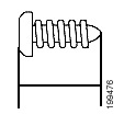
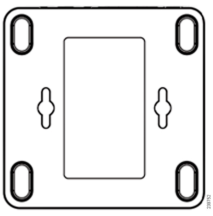
The ATA has two wall-mount slots on the bottom panel. To mount the ATA on a wall, you need mounting hardware (not included). Suggested hardware is illustrated (not true to scale).
Recommended hardware (not included): Two number-six pan-head tapping screws, 5/8-in. length, with anchors for sheet rock installation.
 |
| 5/8 in. (15.8 mm) |
WARNING Insecure mounting might damage the ATA or cause injury. Cisco is not responsible for damages incurred by insecure wall-mounting.
To mount the unit to the wall:
STEP 1![]() Determine where you want to mount the unit. Verify that the surface is smooth, flat, dry, and sturdy.
Determine where you want to mount the unit. Verify that the surface is smooth, flat, dry, and sturdy.
STEP 2 Drill two pilot holes into the surface 58 mm apart (about 2.28 in.).
STEP 3 Insert a screw into each hole, leaving a gap of 5 mm (0.1968 in.) between the underside of each screw head and the surface of the wall.
STEP 4 Place the unit wall-mount slots over the screws and slide the unit down until the screws fit snugly into the wall-mount slots.
Was this article helpful?
That’s Great!
Thank you for your feedback
Sorry! We couldn't be helpful
Thank you for your feedback
Feedback sent
We appreciate your effort and will try to fix the article